Quick Side Quests
Small builds and fast experiments
Standalone Projects
Complete systems built end to end
Under Construction
Active work currently in progress

Back to Under Construction

BeamNG.cad — From SolidWorks to a Tuned Vehicle

I’m developing a repeatable SolidWorks-to-BeamNG workflow for our Baja SAE team. The pipeline now produces a complete, drivable vehicle, and we’ve reached a well-tuned development build through iterative testing of its structure, suspension, steering, and drivetrain.

A Repeatable Simulation Workflow for Baja SAE

Complete vehicle generated; tuning milestone reached · October 2026
In progress
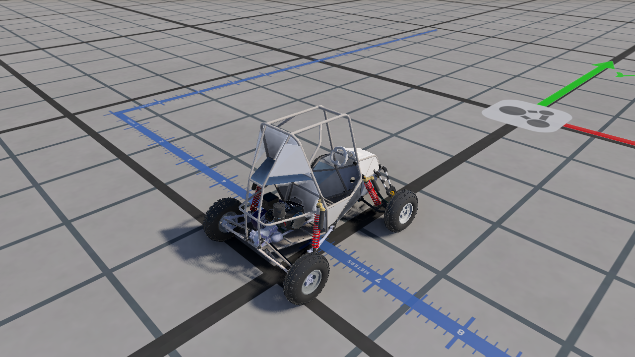
Complete CAD-derived Baja SAE development vehicle in BeamNG, showing the tubular frame, body panels, drivetrain, wheels, and red coilover springs.
A complete CAD-derived development vehicle in BeamNG during the October tuning iterations.

Problem

As our vehicle designs evolve, rebuilding a simulation by hand takes time and specialist knowledge. Student turnover makes that expertise difficult to retain. My goal is to make CAD-to-simulation preparation repeatable so future team members can continue using and improving the workflow.

Solution

I built a SolidWorks add-in in C#, supported by Python geometry, calibration, and vehicle-generation tools. It captures selected CAD components, material properties, and reviewed joint definitions, generates the BeamNG physics structure, connects the visible geometry, and packages the vehicle as a mod.

The workflow now covers the frame, suspension linkages, steering, wheels, drivetrain, and component mounts. Automated tests record vehicle motion and compare suspension behavior with the source CAD geometry, helping identify where the generated model needs refinement.

Current Milestone

The pipeline has progressed from importing a frame to producing a tuned vehicle that can be driven and evaluated in BeamNG.

  • Complete vehicle generation and standalone mod packaging from reviewed CAD inputs.
  • Repeated tests held 18, 36, and 54 km/h without broken beams or reported instability.
  • Controlled suspension loading demonstrated recovery after release, providing measurable evidence alongside driving feedback.

Next Steps

I’m refining physical accuracy using measured shock and tire specifications, improving numerical mass and inertia, and extending validation to more demanding driving and impact conditions. The current build provides a working foundation for that development; correlation with the real vehicle remains ongoing.

From CAD Setup to Measured Behavior
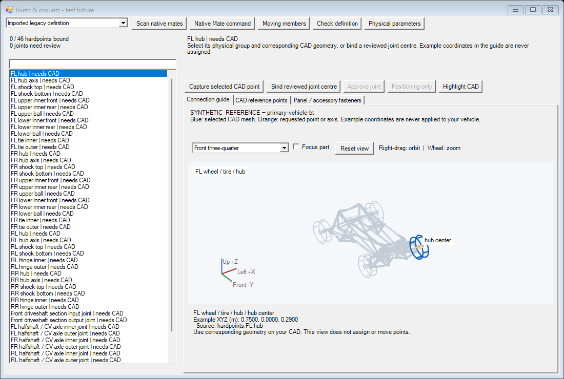
Joint-authoring interface with a hardpoint list and a highlighted front-left wheel hub in the reference vehicle preview.
Defining the mechanism. The add-in connects reviewed CAD references to suspension and steering hardpoints. This interface example shows a test fixture awaiting CAD assignments.
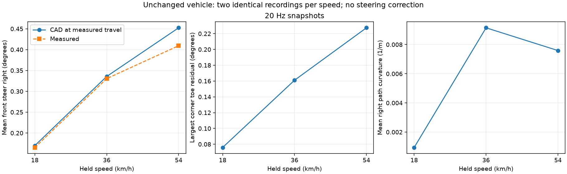
Plots comparing CAD-predicted and measured front steering, toe residuals, and path curvature at 18, 36, and 54 kilometres per hour.
Checking motion against CAD. Two repeat recordings at each speed produced identical driving telemetry. Measured front steering closely followed the CAD prediction at the observed suspension travel; these tests also recorded the remaining curved path.
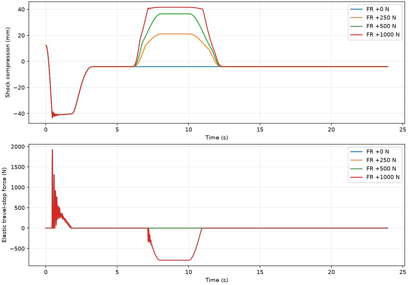
Shock compression and travel-stop force over time for zero, 250, 500, and 1,000 newton front-right hub loads, showing recovery after release.
Loading and recovery. The front-right suspension returned to its pre-load state after controlled loads up to 1,000 N. These bounded tests demonstrate recovery in the simulation; real-vehicle correlation remains ongoing.
Tags Baja SAEBeamNGIn progress
Baja SAEBeamNGIn progressJBeamAutomationKnowledge transfer
Skills SolidWorks APIC#/.NETPython
SolidWorks APIC#/.NETPythonGeometry processingVehicle simulationAutomated testing